New "Simple Spectrum Analyzer" device: meet the D6 JTGP-1033
Hi,
Some of the users of my VMA Simple Spectrum Analyser software have pointed out that there is this rather new device being sold on AliExpress:
https://www.aliexpress.com/item/Simple-Spectrum-Analyser-D6-with-Tracking-Source-T-G-V2-02-Simple-Signal-Source/32968659654.html
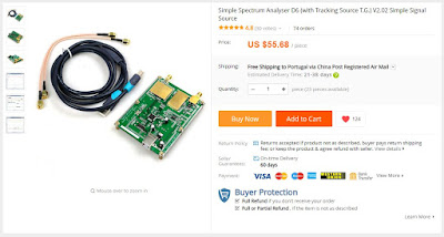
The first thing that strikes the eye is the price of just US$55.68/€49.98 and that includes shipping!
And yes, it comes with two ADF4351, which means that this device is a direct competitor to the NWT4000 - at less than the third of the price! How is that even possible?
Well, I ordered one to check it out...
I had to wait a long time for the package to arrive, due to the fact that I placed the order on the first day of Chinese New Year holidays (they deserve holidays, too), which meant that the order took two weeks to get processed. Another month later, it arrived without having gone through customs, which was nice.
The package included:


Important: These STL files are for board revision 2.03. It seems that there is a newer revision 2.03B, which has a different footprint. Measure your board before printing this case. If your board is not 99mm x 74mm then this case will not work.
Some of the users of my VMA Simple Spectrum Analyser software have pointed out that there is this rather new device being sold on AliExpress:
https://www.aliexpress.com/item/Simple-Spectrum-Analyser-D6-with-Tracking-Source-T-G-V2-02-Simple-Signal-Source/32968659654.html

The first thing that strikes the eye is the price of just US$55.68/€49.98 and that includes shipping!
And yes, it comes with two ADF4351, which means that this device is a direct competitor to the NWT4000 - at less than the third of the price! How is that even possible?
Well, I ordered one to check it out...
I had to wait a long time for the package to arrive, due to the fact that I placed the order on the first day of Chinese New Year holidays (they deserve holidays, too), which meant that the order took two weeks to get processed. Another month later, it arrived without having gone through customs, which was nice.
The package included:
- one D6 device - just the PCB without any case, as shown in the folloowing two pictures
- one rather high quality USB cable
- two SMA cables
- a small bag with three M810 IC's - note that these are the components that break if you attach a DC current to the IF or if you exceed the maximum input power (I think it is +10dBm, but I normally don't dare to go above 0dBm)
Here are two pictures of my D6 PCB:


It seems I got the v2.03 revision. I know there is a V2.032 revision, too, but I have no clue what changed.
Also, when the order was processed, I received a download link that included the usual WinNWT/LinNWT software that Chinese sellers bundle with this range of devices.
Note that this is not legal, as the author of WinNWT/LinNWT has not given any permission for them to do so. On a side note, the author (DL4JAL) of this software removed it completely from his website! I assume he got fed up with all inquieries of unhappy users, when he did not have anything to do with it! WinNWT/LinNWT was programmed in the context of German "Funkamateur" magazine (https://www.funkamateur.de/) for the NWT-9 and NWT-500 range of original devices.
Interestingly and to my great surprise, the provided arquive did include much more! It has the full SDK of the D6, including schematics and even the source code of the firmware!
It actually gets even stranger, as the arquive included the SDK for a whole range of other RF products, commonly sold by Chinese online sellers.
And, yes, the archive included Keil (https://www2.keil.com/stmicroelectronics-stm32), along with a keygen to activate it...
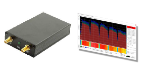
Anyway, I hooked up the D6 and started my software and the first thing I noticed is that my software freezes in the middle of the first sweep. After restarting my software, the sweep works fine and noticably faster than with SMA/NWT devices. The refresh rate is about 3 times faster, so you get an almost real-time spectrum (about 1-2 FPS). And it does not matter if you select 500 or 1000 samples.
Wow.
But unfortunately, the second thing I noticed is that the noise floor is at around -70dBm, that is 10dB more than the SMA/NWT devices). Thus, the sensitivy is much lower.
The following two pictures compare the same signal measured with the SMA and the D6:

Picture 1: DVB-T transponder at 754MHz as seen by the D6

Picture 2: DVB-T transponder at 754MHz as seen by the SMA
Another particularity of the D6 is that the TG (Tracking Generator) functionality is activated by a small button on the PCB, rather than being always on like on the NWT.
It does work and my initial tests were to my satisfaction. Finally a cheap device that allows antenna tuning and filter measurement!
Task #1: Fix my software to support the D6 without the freezes. I am happy to say that this has been done and you can download a new version of my software with support for the D6! You need to select this device in the SETUP tab (it is the last on the list).
Task #2: Try to compile the firmware source code. After some struggling I was able to set everything up and I am now able to compile the source code. This will allow me to try to implement a few changes to hopefully speed up the spectrum refresh rate.
Task #3: Flash the compiled firmware. This requires a programmer like this one:
Warning: Don't buy the cheapest offer of this kind and make 100% sure that you are buying the ST-Link V2 device. My first purchase arrived, but I got a simple USB-RS232 PLL interface, which looks exactly the same. Got a refund from eBay, but still annoying! Look at all the pictures of the offer, as often the first picture shows the ST-Link V2 but the other pictures show what you will be really getting...
After getting hold of the ST-Link V2 (clone) and downloading the ST-LINK Utility (Freeware), I tried to program the device - but it took me a while and with the help of my friend CT2IOK, who told me the correct pin-out, I was finally able to flash the firmware I compiled. That was of course after reading out the original firmware (no protection, thank God!).
Here is the connection diagram:

Looking at the JTAG connector on the PCB, you will see pin 1 identified with the "+" symbol (3.3V).
Connect the ST-LINK V2 as follows:
SWDIO > 4
GND > 3
SWCLK > 2
3.3V > 1 (+)
So we now have a working original firmware backup and the possibility to change/improve the firmware. Great!
In fact others have already started to do so: https://github.com/joseluu/D6_firmware
This left me with the bad performance of the D6. But I was pointed to this great development:
David F4HTQ describes how he modified the D6 and got an astonishing improvement, that makes the D6 rival the NWT!
David is the author of "SNA Sharp", another software that interfaces the SMA/NWT/D6 class of devices. Make sure to try it out; http://alloza.eu/david/WordPress3/?page_id=478
Another modification was done by CT2IOK: he replaced the 25MHz TCXO with a better one (FOX924), which improved frequency stability and resulted in a correct frequency reading.
I have to implement these modifications when time allows, but meanwhile I made a case for the D6:


I printed it using the Markforged printers in our office: https://markforged.com/
If you want to try and print the case yourself, here are the required STL-files. Note that you need a rather good quality printer precision-wise, as the STL files are a close fit for the PCB and leave only 0.5 mm margin around it.
Important: These STL files are for board revision 2.03. It seems that there is a newer revision 2.03B, which has a different footprint. Measure your board before printing this case. If your board is not 99mm x 74mm then this case will not work.
Let me know about your own modifications, enhancements, etc., on this very promising device!
Regards,
Vitor

Thank you for this post Vitor.
ReplyDeleteA new version os SNASharp is available.
All the informations ( in french sorry) here:
http://alloza.eu/david/WordPress3/?p=677
Great!
ReplyDeleteRegards,
Vitor
pinout seems to be wrong. Its 3V3,GND,SWDIO,SWCLK on my device
ReplyDeleteThank you. I will need to verify - I might have made a mistake.
DeleteHi, Vitor, great post!
ReplyDeleteI have an Aliexpress unit. Where to find link for firmware and schematics?
Send me an email.
ReplyDeleteHi Vitor,
ReplyDeleteI am planing to buy such board like D6 from aliexpress. There is another board which is cheaper.(https://s.click.aliexpress.com/e/pWgTwM5E). Can you suggest me the better one?
Also, can you share result(screenshot) after updates as suggest by David.
BR
Rakesh
Both the D6 and LTDZ are worse than the original SMA/NWT devices.
DeleteThey have higher background noise (-70dBm instead of -80dBm) and less sinsitivity.
I prefer the D6 over the LTDZ.
Both have faster sweep rates than the SMA/NWT devices, but again, this comes as the price of less sensitivity.
I think that the SMA/NWT devices are worth the extra cost.
Same answer as Visitor for me.
Deletethe LTD share the same schematic with the D6, but the mixers are not shielded that increase the EMI.
Prefer the D6.
I removed the oscillator, I have a 10Mhz GPS, so I divided it by 2 using a 74HCT74 and multiplied it by 5 using an ICS-501. This resulted in a GPS locked analyzer with high frequency accuracy.
ReplyDeleteCool! Thanks for the info!
DeleteMay have done something stupid. I own a V2.032B version of the board. Programmed it with modified firmware. Now it seems to scan the spectrum but output is a flat line Across the spectrum with an extreme out of range value. Tried with Simple Spectrum Analyzer and SNASharp, no joy. Made a backup of the firmware (i thought) but the file seems corrupt.
ReplyDeleteIs there some calibration to be done or could somebody provide me with a backup of the original firmware for the V2.032B board. Any input is welcome.
Thank you in advance, Huub
Hello,
DeleteI uploaded my backup (BIN and HEX format) here: https://www.mediafire.com/file/44pu4hctoa3xcgj/FW--203.zip/file
Please try it should fix your device.
Regards,
Vitor
Not sure where my previous reply went so post a new one. Thnk you for providing the files. Sorry to say that version didn't work either. After some measurements i came to the conclusion the AD converter wasn't enabled. There is A trace from cpu to AD enable pin. No signal on that line so i shorted enable to + as on the original schematic. That did the trick. All versions i have, including the modified ones work. Thanks again!
DeleteThank you for these details Huub.
DeleteI Have just a question, have you tested your analyzer before programming a new firmware ? and if this is the case, could you tel me is he was working ?
Regards,
David.
Hi David, Yes i did and yes it worked. Tested it on both VNA an SNASharp. After primary testing i first programmed it with a version from joseluu (beta5 i think) After that the input stopped working and none of the available versions of the firmware did help. More specific, there was no input signal but the tracking generator for example did work. Can't post an image but made one. The image shows the trace from STM pin 4 to AD - Enable. In the end the trace was cut and I shorted the AD converter en-pin with plus (6 - 7) like on the 203.2 board.
DeleteRegards Huub
to see the difference between two boards look at the pictures of the boards from this AliExpress seller.
Deletehttp://s.aliexpress.com/ZFfUviaa
First picture is the 2.03B and second is 2.03A. The trace from the stm32 pin4 to the Ad-converter is missing on the 2.03A board. Enabling the line surely is done by firmware. So probably a software solution is best. sadly couldn’t find the time to setup an enviroment to modify and compile a modified version. Posting this for future reference and hope it helps defelopers.
Huub
Hi Vitor,
ReplyDeletedo you have case work for new revision 2.03B 82mmX99mm board.
Regards,
Sua , TA2AD
Unfortunately I have not.
DeleteHi Vitor
ReplyDeleteDo you have the schematic for the D6? the aoftware I received does not have it, perhaps you could make a link for download. Thank you Paul
I cannot post a download link, because I don't own the intellectual property of the schematic. Regards,
DeleteVitor
Hi Vitor
DeleteAbout the schematic of the D6! et al...
The goodies that came with it as well...
Cheers
Colin
I am trying to find out if the D6 supports a second external sensor input, like the NWT500 for example, and where this would be found on the PCB. I can see there is no connector but maybe it is peresent in the firmware and needs only to be connected. Does anyone know the answer to this? Thank you Paul
ReplyDeleteThe hint was for you to drop me an email...
DeleteHi Vitor, just to follow up my enquiry, after examining the schematic it seems there is no hardware provision for a channel two input. It may be possible but the PCB would need to be altered so, at present, no is the answer. Thanks for your help.
ReplyDeleteI am just mounting the board in a nice aluminium box from aliexpress and performing the modifications that David has suggested. I hope to finish and test it soon. Cheers Paul
Hi Paul, can you provide the link to your Aluminium case?
ReplyDelete