Error Mapping the SMA/NWT/D6/LTDZ devices
Hi,
I just released a new version of my software (Version 2019-08-30) with improved algorithm for the error mapping.
I fixed some bugs and added support to save calibration settings in the Registry.
This is what the error map looks like as a graph made with Excel:
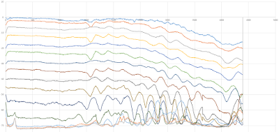
As can be clearly seen, some reagions of the graph have overlapping curves. In this reagion, my error map compensation algorithm will have no way to apply the correct attenuation.
The graph shows the actual error map: the first point is the correct power level for each trace (0dB, -5dB, -10dB, etc.). The algorithm will extract from each trace the respective correction value.
Creating an error map is really easy and quick, but requires a mean to provide calibrated input signal at each power level over the whole frequency range that is to be calibrated.
You can choose if you want to export each trace as LIVE, MIN, MAX, AVG or MATH (only Live and AVG make sense, though).
Another new feature is the external attenuation correction: you can specify a value that shifts the trace up or down, according to the dB value inserted. This should be interesting for those that modified the D6 device for improved performance and now have a +10dB to high reading.
Here are some examples of the benefits of using the error map compensation:


Please test this new functionality and let me know about your results in the comments.
Regards,
Vitor
I just released a new version of my software (Version 2019-08-30) with improved algorithm for the error mapping.
I fixed some bugs and added support to save calibration settings in the Registry.
This is what the error map looks like as a graph made with Excel:

Sequencial spectrum traces (35MHz-4.4GHz) captured with increased attenuation (in 5dB steps).
As can be clearly seen, some reagions of the graph have overlapping curves. In this reagion, my error map compensation algorithm will have no way to apply the correct attenuation.
The graph shows the actual error map: the first point is the correct power level for each trace (0dB, -5dB, -10dB, etc.). The algorithm will extract from each trace the respective correction value.
Creating an error map is really easy and quick, but requires a mean to provide calibrated input signal at each power level over the whole frequency range that is to be calibrated.
You can choose if you want to export each trace as LIVE, MIN, MAX, AVG or MATH (only Live and AVG make sense, though).
Another new feature is the external attenuation correction: you can specify a value that shifts the trace up or down, according to the dB value inserted. This should be interesting for those that modified the D6 device for improved performance and now have a +10dB to high reading.
Here are some examples of the benefits of using the error map compensation:

Orange Trace: -16dBm Signal without error map compensation
Green Trace: -16dBm Signal with error map compensation

Orange Trace: Local DVB-T transponder without error map compensation
Green Trace: Same DVB-T transponder with error map compensation. The LIVE trace is now useable and with the AVG trace measurements are possible. In this case the automatic transponder recognition, showing the correct center frequency of 754MHz.
Please test this new functionality and let me know about your results in the comments.
Regards,
Vitor

Awesome work.
ReplyDelete